TANDEM MONSTER FLAPPER
This monster owes it's existence to this blog. While writing the initial helicopter blogs I realized that I did not have a version of a tandem helicopter, which is the dominant configuration for heavy lifters. This seemed to be a suitable mechanical challenge. So hopefully I will feel complete after this blog - maybe.
The scene is set in an African village, sort of. I decided that hessian would create a suitable neutral background. This helps with the camera auto exposure (when compared with the white or black background). It also hints towards of a high veld grassland, which could be considered its natural environment. I felt a need to build a corrugated iron hut as part of the background and to create the mood. Unfortunately I also added a Baobab tree, which occurs to the North of country and would die in a high veld winter. But it does add an African feel.
The overall view shows the twin rotors of the tandem flapper, which are placed one behind the other (my previous dual rotor helicopter had the rotors next to each other). The challenge was to design a mechanism which would turn the rotors in opposite directions (counter rotating), and flap them up and down twice every revolution.
The flapping mechanism consists of a rod which runs inside the rotor shaft. This is done to limit the number of mechanisms which are external the main helicopter shape (a refinement of the first 2 flapping helicopters). The up and down motion is transferred from a lever which moves up and down via 2 discs attached to the rod. Thus allows the rod to turn with the rotors, as well as move up and down.
The up and down motion is transferred to the rotor blades with an arm attached to the top of the rod and blades via wire links. The blades are hinged around the top bearing, which allows them to flap up and down. The rod and arms need to rotate with the blades, and therefore the complicated rotating cone couple at the bottom of the rotor mast.
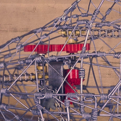
The counter rotating chain drive for each rotor is driven by a chain from the wheels axle. It goes through a right angle drive to get the chains in the correct orientation for the rotors. A simple gearbox out of thin flat bar with silver soldered brass bushes hold the axles for the counter rotating gears. The drive chains rotate at the same speed as the main axle. The gears were sourced from a robotics shop. The chain drive gears where cast from epoxy many years ago.
To provide 2 rotor flaps per revolution, a 2:1 ratio gear box is driven from the main shaft. This drives cranks for the rotor flappers. The cranks are out of phase with each other, so that the rotors do not move together (not strictly necessary because the same can be achieved by adjusting the "timing" with the chain drives). But it does look good when its moving.
The final mechanism was built to move the head of the pilot. With all the chains and gears dedicated to the flapping mechanism, I did not feel like adding additional drives for my usual head drive, so I tried a cam instead (as seen driving numerous automatons). The cam was made out of wood (seemed liked a good idea at the time). The cam drives a copper dome on the end of a push rod to try and get the mechanism to have relatively low friction. I had to add a small spring as gravity was not enough to keep the push rod tracking the cam. The spring is not very stiff, so overall the mechanism moves relatively smoothly.
So that's about it. The blog created the inspiration for the tandem configuration, and watching other peoples automaton videos inspired the cam mechanism. The power of modern communication. Hope you enjoy the video more after this explanation.


